Use 3rd party Hardware for 'Avise'
The 14.7456 MHz version for ATmega32 is well suited to be used
together with the low-cost "Mega32 prototype board" from "embedit.de"
Build Your Own Hardware for 'Avise'
(updated 12 February 2006)
The printed circuit boards presented here are kept quite simple due to the fact that most people who are interested to check out the possibilities of microcontrollers don't have the tools to produce sophisticated PCBs.
When the hardware has been built up, the next step is to burn the program code of Avise into the CPU flash memory. To perform this, you need a serial programmer, which is temporarily connected with a ribbon cable to the Avise hardware.
PCB for ATmega168 or ATmega8(L)
The first proposal to run 'Avise4.2' is made for a minimum setup with the ATmega168 or (less preferred) ATmega8(L) CPU.
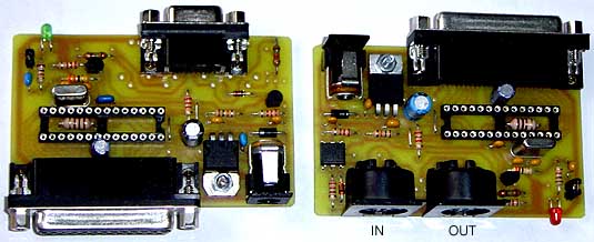
As a special feature, this board provides a dual layout for a RS-232 and a MIDI command interface, which can be assembled as an alternative. Next to the LED, there is a jumper for selection of different baud rates (checked only once during power up). So we have the following options:
Building this part is not tricky, anyway. Standard parts without special features are used. All capacitors must be ceramic types except the electrolytic ones. Jumper wire BR1 is only necessary for ISP programming via the 25 SubB connector. Jumper bridge BR2 connects the application interface with unregulated power and should only be inserted when really needed. If assembled, there is a certain risk to destroy the microcontroller with overvoltage. Depending on the desired direction of current flow, either a wire or a diode can used. Choke coil L1 is placed below the microcontroller.
Following CPU pins are optionally used for special functions:
For easy handling, the board is completed with a 5 volt regulator and a DC IN connector for common wall plug adaptors (recommended: 9 volt unregulated). The PCB footprint fits to the connector from manufacturer "ROKA", Conrad Electronic order nr. 73 79 92. Pads for a simple clamp are provided, too.
The I/O lines of the microcontroller and supply voltages are wired to a 25 pin SubD female connector, which is wired to the microcontroller pins as follows:
With a special adaptor cable, the MIDI interface can be connected to a standard PC COM port. So programming is easy with 19200 baud, but later the programmed module can serve as an interactive MIDI music instrument, for example.
Jumper missing: baud rate 19200
Jumper placed: baud rate 31250 for MIDI
Jumper missing: baud rate 19200
Jumper placed: baud rate 115200
PortD,4: LED and baud rate sensing.
This pin is not available for user I/O! If you are using your own hardware construction, please note: never connect this pin directly to signal ground, use a resistor about 1 to 2 Kiloohm instead - or the LED configuration as shown in our schematic. If at power up this resistor is pulled to ground, the microcontroller starts with the default baud rate. If the resistor is connected to +Vsupply, the microcontroller starts with the alternative baud rate. This behaviour is emulated dynamically with the capacitor, which may be added by jumper in our design.
PortD,2: CNT0 input -- PortD,3 additionally used as sense for ENC0 count up/down
PortB,0: CNT1 input -- PortD,7 additionally used as sense for ENC1 count up/down
PortB,1: PWM1 and WAVE output
PortB,3: PWM2 output
PortB,4: SDA for I2C functions, needs an external pull-up resistor about 10 Kiloohm
PortB,5: SCL for I2C functions
Normally Ports B3 to B5 do not conflict with a programmer, except the user hardware does burden the programmer and microcontoller with low impedance inputs (lower than about 1 kiloOhm).
Pin1 = unreg. supply
Pin14 = PortD,3
Pin2 = reset
Pin15 = PortD,2
Pin3 = PortC,5
Pin16 = PortC,4
Pin4 = PortC,3
Pin17 = PortC,2
Pin5 = PortC,1
Pin18 = +5 volt regulated
Pin6 = PortC,0
Pin19 = +5 volt regulated
Pin7 = signal ground
Pin20 = signal ground
Pin8 = PortB,5
Pin21 = PortB,4
Pin9 = PortB,3
Pin22 = PortB,2
Pin10 = PortB,1
Pin23 = PortD,6
Pin11 = PortD,7
Pin24 = signal ground
Pin12 = PortB,0
Pin25 = signal ground
Pin13 = PortD,5
This connector may be used for "in system programming" of the microcontroller, too:
--- Pin 2 = uCPin 1 = reset
--- Pin 8 = ucPin 19 = PB5 = SCK
--- Pin 21 = uCPin 18 = PB4 = MISO
--- Pin 9 = uCPin 17 = PB3 = MOSI
--- Pins 7,20,24,25 = signal ground
--- Pins 18,19 = +5 volt regulated
For programming the ATmega8, following setting of the "fuses" is recommended: for 3 volt operation only program BODEN, for 5 volt operation program BODLEVEL, too. For some crystal types programming of CKOPT may be necessary. All fuses else should be left unprogrammed (setup for "slowly rising power").
For programming the ATmega168, following setting of the "fuses" is recommended: for 3 volt operation only program BODLEVEL1, for 5 volt operation program BODLEVEL0, too. All fuses else should be left unprogrammed (setup for "crystal oscillator with slowly rising power"). If this does not work - especially with a crystal frequency above 8 MHz - try with CKSEL3 programmed.
Circuit Diagram
RS-232 and MIDI only can be assembled as alternatives. Together with the RS-232 interface R7,D3 and IC3 are not used and R8 is 1.5 kiloOhm. When the board is built for MIDI, then R5, D2 and T2 are omitted and R8 is 220 Ohm. J1 must be placed then.
The PCB layout drawing and the assembly drawing have been put into separate files. When making your own films, be careful to print it with exact 100% size. The board size is exactly 80x50mm, so 4 of them will fit on a 160x100 mm "eurocoard".
PCB for ATmega32:
The second proposal is a design to run 'Avise4.2' with an ATmega32(L) CPU. The PCB design is copied from the previous version of 'Avise', so it is labelled for an AT90S8535 CPU and with an external serial EEPROM for program storage. Don't care for these legacy features: leave away the EEPROM and the burn out detector IC4 and the board is 100% compatible for the actual version.
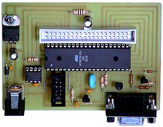 PCB assembly with simple RS-232 interface. |
This PCB layout is held strictly in 2.54 mm raster, this way - if no PCB can be etched - it is possible to wire the circuit completely 1:1 on a prototyping board with pad matrix (german: "Lochrasterplatte"). Example see below |
Following CPU pins are optionally used for special functions:
PortD,2: CNT0 input -- PortB,6 additional sense for ENC0 count up/down
PortD,3: CNT1 input -- PortD,4 additional sense for ENC1 count up/down
PortD,5: PWM1 and WAVE output
PortD,7: PWM2 output
PortB,1: SDA for I2C functions, needs an external pull-up resistor about 10 Kiloohm
PortB,0: SCL for I2C functions
The layout of the ISP connector at this board is compatible with the 10 pin cable of AVRISP and STK500.
For programming the ATmega32, following setting of the "fuses" is recommended: for 3 volt operation only program BODEN, for 5 volt operation program BODLEVEL, too. For clock frequencies above 8 MHz programming of CKOPT is necessary. All fuses else should be left unprogrammed (setup for "slowly rising power").
For easy handling, the board is completed with a 5 volt regulator and a DC IN connector for common AC/DC adaptors (recommended: 9 volt unregulated). This connector does not exactly fit into the 2.54 mm matrix (manufacturer "ROKA", Conrad Electronic order nr. 73 79 92). In case, it can be replaced with a simple clamp.
I/O signals can be connected via a 40 pin IDC ribbon cable (IDE harddisk cable). The ceramic resonator must be a three pin type with built-in capacitors, max. frequency error 1%. If you want to use a crystal, additionally fix two ceramic capacitors 22pF below the board.
Circuit Diagram
The the PCB layout drawing and the assembly drawing have been put into separate files. When making your own films, be careful to print it with exact 100% size.
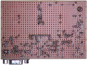 |
Here - as a hint for lowtech production - the circuit described above has been built 1:1 on a prototyping board. For wiring a solid silver plated copper wire with 0.5 to 0.6 mm diameter is recommended.
If only a subset of parts or I/O connections is needed for a certain application, wiring the prototyping board takes less work, of course. As I/O connections are not necessary for a first test, they have been left away, but can be added later as needed. Some application specific hardware can be added on the prototoyping board, too. |
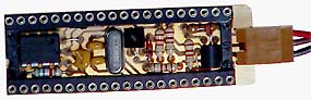 Another funny example is shown - how the same circuit can be made miniaturized like a "Basic Stamp" with standard thru hole parts. The PCB is made of 0.5 mm epoxy material. The holes for the microcontroller socket are drilled with 1.7 mm diameter, so the PCB fits smoothly below the socket. The RS-232 interface is included, 3 wires lead separately to a SuBD connector. Power is supplied via the microcontroller socket.
* All information within this text and the related ones is believed to be correct, but published without any warranty and under exclusion of any responsibility
* Trademarks and product names cited in this text are property of their respective owners.